
Abstract
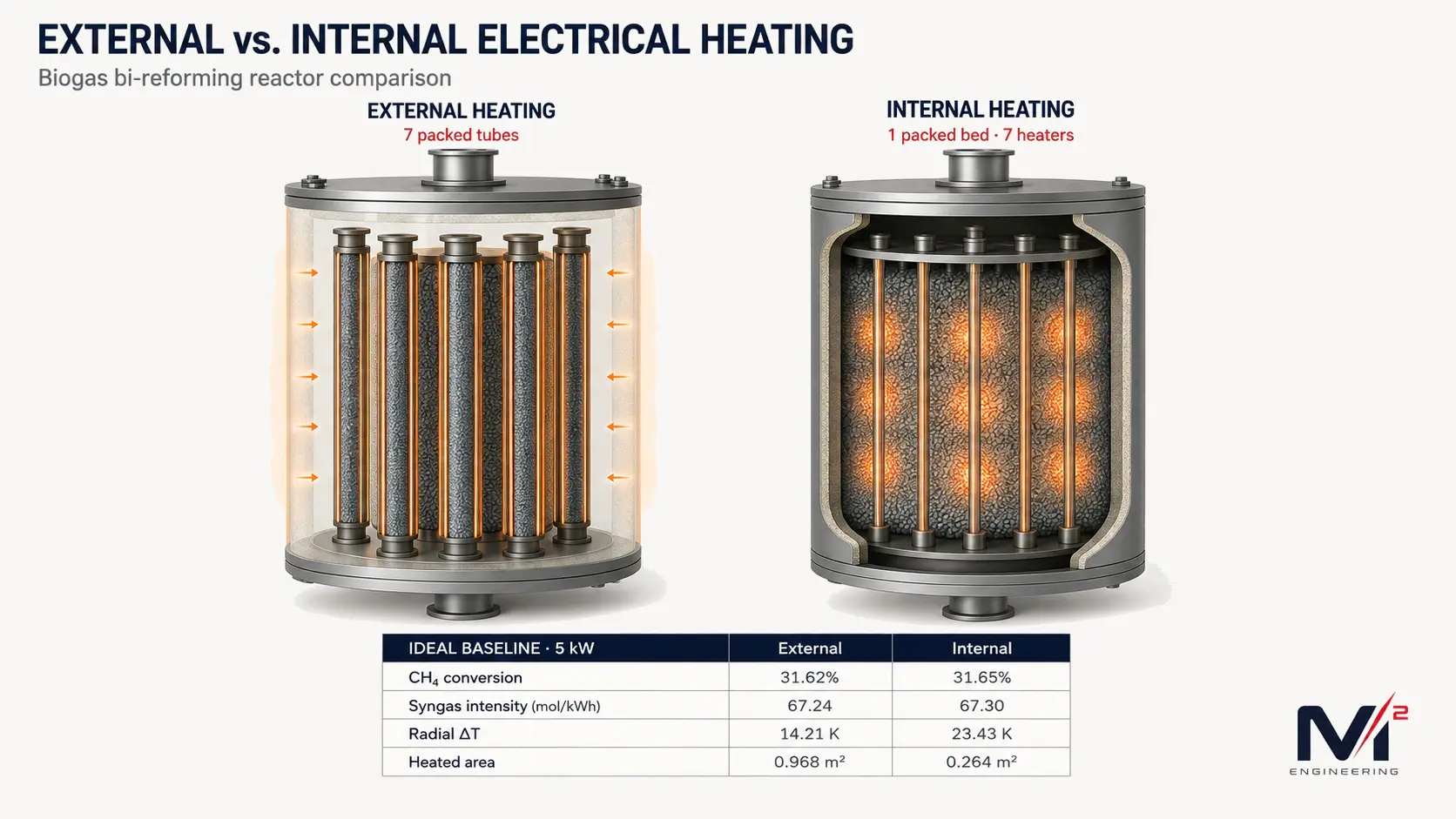
Electrification changes how heat can be introduced into reforming reactors. Instead of transferring all of the required energy through an externally heated wall, electrical heaters can also be placed directly inside the catalyst bed. For strongly endothermic reactions such as biogas bi-reforming, internal heating appears attractive because the heat source is physically closer to the reacting catalyst. We tested that assumption by comparing two electrically heated packed-bed reactor architectures: seven externally heated catalyst tubes and one larger packed bed containing seven distributed internal electrical heaters. Catalyst inventory, active length, feed basis, pressure, inlet temperature, and electrical power were kept the same so that the comparison remained focused on the heating architecture itself. Under ideal insulation, both reactors produced almost the same methane conversion and syngas intensity, but their thermal behavior was quite different. The external tubes provided much more heated area and lower heat flux, while the seven-heater internal reactor required a higher source temperature and developed a larger radial temperature spread. Increasing the internal heater count changed that result substantially, and once environmental heat loss was introduced, compact packaging gave the internal reactor an advantage under the selected heat-loss assumptions. The comparison therefore points away from a simple external-versus-internal conclusion. Heater location matters, but heated area, source-to-catalyst distance, local heat flux, catalyst transport, pressure drop, and the reactor thermal envelope matter just as much.
Reactor Configurations and Modeling Basis
The baseline reactor length is 2.0 m, with 5.0 kW electrical input, 923.15 K inlet temperature, 500 kPa absolute pressure, and a wet-feed GHSV of 3000 h⁻¹. The wet feed contains 37.31% CH₄, 24.88% CO₂, 37.31% H₂O, and 0.5% H₂ by mole, with no CO at the inlet. The total wet feed is 0.197862 mol/s, including 0.0738274 mol/s methane. Catalyst volume is fixed at 0.00532186 m³, corresponding to 4.78967 kg at a bulk density of 900 kg/m³. The external reactor divides this catalyst among seven 22 mm-ID packed tubes with 2 mm walls, while the internal reactor uses seven 6 mm sheathed heater elements inside a larger shell; the shell is enlarged so that heater displacement does not reduce catalyst inventory. The model itself was deliberately kept reduced-order rather than trying to reproduce every three-dimensional feature of a manufactured reactor. Gas flow and reaction were treated as steady one-dimensional plug flow, while radial heat transfer was represented separately so that packed-bed conduction, wall or sheath resistance, and heater-to-bed contact resistance could remain explicit. Both architectures use the same effective radial conductivity, with 1.5 W m⁻¹ K⁻¹ as the baseline and 0.75–3.0 W m⁻¹ K⁻¹ propagated because packing, radiation, pressure, flow dispersion, and contact can change the effective value substantially. Wall and sheath conductivity are 16 W m⁻¹ K⁻¹, and the nominal contact conductance is 350 W m⁻² K⁻¹. Pressure drop is calculated with the Ergun relation using local gas density and viscosity, a bed void fraction of 0.40, and 3.2 mm equivalent pellets. Beyond the equal-5-kW baseline, the study also solves equal-conversion power requirements, matches heated area, and varies the number of heat sources so that the ranking does not depend on one geometric comparison alone.
The chemistry was treated on the same basis for both reactors. The reaction network contains steam methane reforming, water-gas shift, and dry methane reforming, with gas enthalpy, heat capacity, Gibbs energy, equilibrium constants, density, viscosity, and conductivity evaluated consistently with Cantera using the GRI-Mech 3.0 NASA7 thermodynamic and transport dataset. During the final audit, the provenance of the supplied dry-reforming expression was corrected: it belongs to a Verykios-family Ni–La₂O₃ formulation rather than the later ACS Catalysis model with which it had initially been associated. The supplied expression was retained so that the established project basis was not changed after the fact, but the comparison was repeated using K1, containing SMR and WGS, and K3, containing SMR, WGS, and DRM. Both retained the same architecture ranking at the baseline. That is useful evidence that the comparative result is not being driven by one reaction pathway alone, but it is not experimental validation of a single catalyst system at 5 bar. The kinetic framework combines literature expressions developed under different catalyst and operating domains, and pellet-scale diffusion was not resolved with a dedicated intraparticle model. Reaction effectiveness was therefore treated as an engineering uncertainty rather than a measured catalyst property, which means absolute reaction rates and conversion should be interpreted more cautiously than the relative architecture trends. Reaction-specific Q/K and chemical affinity were used to describe the approach to equilibrium because a single conversion-to-equilibrium ratio is not meaningful for a coupled multireaction system. Carbon formation was also screened using graphite thermodynamic affinities; these indicate thermodynamic tendency only and should not be interpreted as coke deposition rates or catalyst life predictions.
Heated Area and Thermal Distance
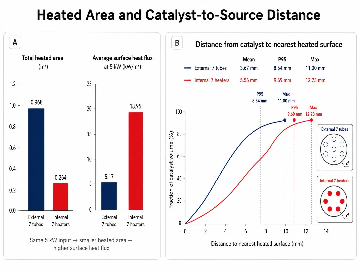
The first important difference appears before any reaction result is examined. The seven externally heated tubes provide 0.96761 m² of heated surface, while the seven internal heaters provide only 0.26389 m². At the same 5 kW input, the corresponding average surface heat flux therefore rises from about 5.17 kW/m² externally to 18.95 kW/m² internally. The catalyst-to-source distance tells the same story from another direction. For the external baseline, the mean, 95th-percentile, and maximum distances from the catalyst to the nearest heated surface are 3.67, 8.54, and 11.00 mm; for the seven-heater internal bed, they increase to 5.56, 9.69, and 12.23 mm. Moving the heat source inside the reactor has therefore not automatically moved heat closer to most of the catalyst. Under ideal insulation, methane conversion is 31.62% externally and 31.65% internally, while net syngas intensity is 67.24 and 67.30 mol/kWh. Chemically, the two baseline cases are effectively tied. Thermally, they are not. The external case develops a maximum radial temperature spread of 14.21 K and a source temperature of about 948 K, while the seven-heater internal case reaches 23.43 K and about 990 K. These radial spreads are model predictions and depend on the assumed effective packed-bed conductivity and contact treatment, but the relative trend is consistent with the much smaller heated area and higher local flux of the seven-heater internal arrangement. When the internal configuration is expanded to 19 heaters and its heated area is matched to the external case, the mean, P95, and maximum thermal distances fall to 2.43, 5.47, and 7.63 mm. In this comparison, distributed heated area matters more than the simple fact that the heater sits inside or outside the bed.
Thermal Behavior and Ideal Conversion
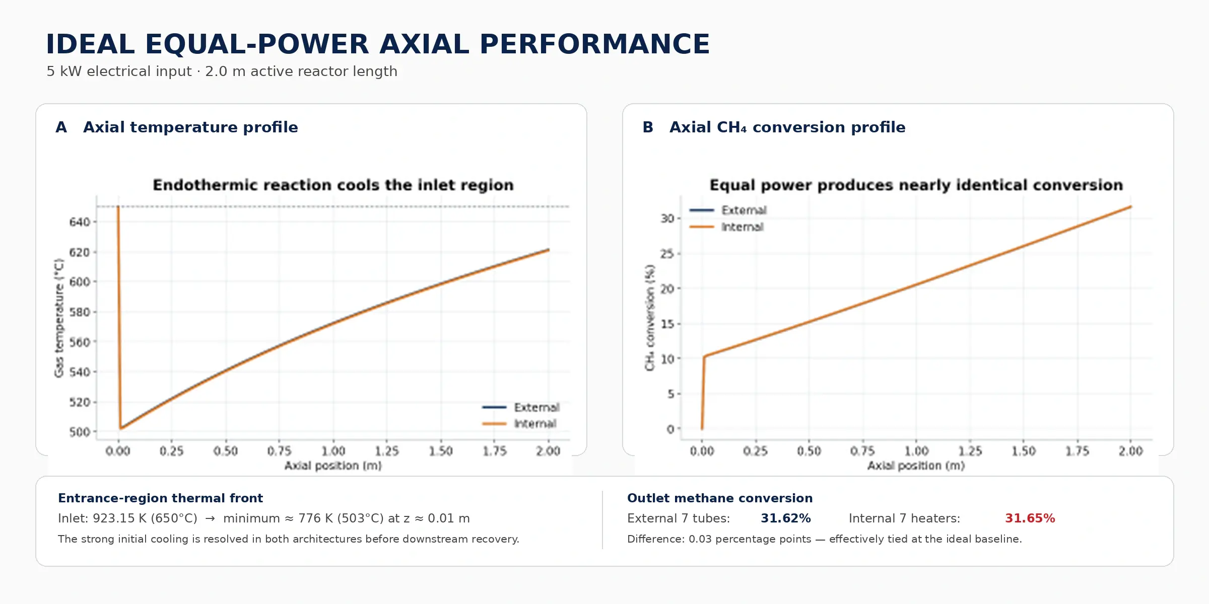
Both architectures also develop a pronounced inlet thermal front. The gas enters at 923.15 K, and the reacting model falls to approximately 776 K near z = 0.01 m before recovering downstream. The location and minimum remain essentially unchanged when the maximum solver step is reduced from 50 to 5 mm at tighter tolerances, while a reaction-disabled case heats monotonically. The feature is therefore numerically resolved within the present model rather than being a simple integration artifact. Its physical magnitude is less certain. Axial solid conduction, solid thermal storage, and separate gas and catalyst temperatures are not resolved, and pellet-scale transport can also influence how quickly the strongly endothermic reforming reactions consume heat near the inlet. For that reason, the 776 K minimum should not be interpreted as a predicted hardware temperature. It is more useful as an indication that the entrance region may become an important coupled reaction–heat-transfer zone that deserves direct measurement. The same caution applies to the exact radial ΔT values. The reduced-order model is strongest when comparing both architectures under the same thermal and kinetic basis, not when assigning design limits to unmeasured packed-bed properties.
Source Distribution and Operating Trade-Offs
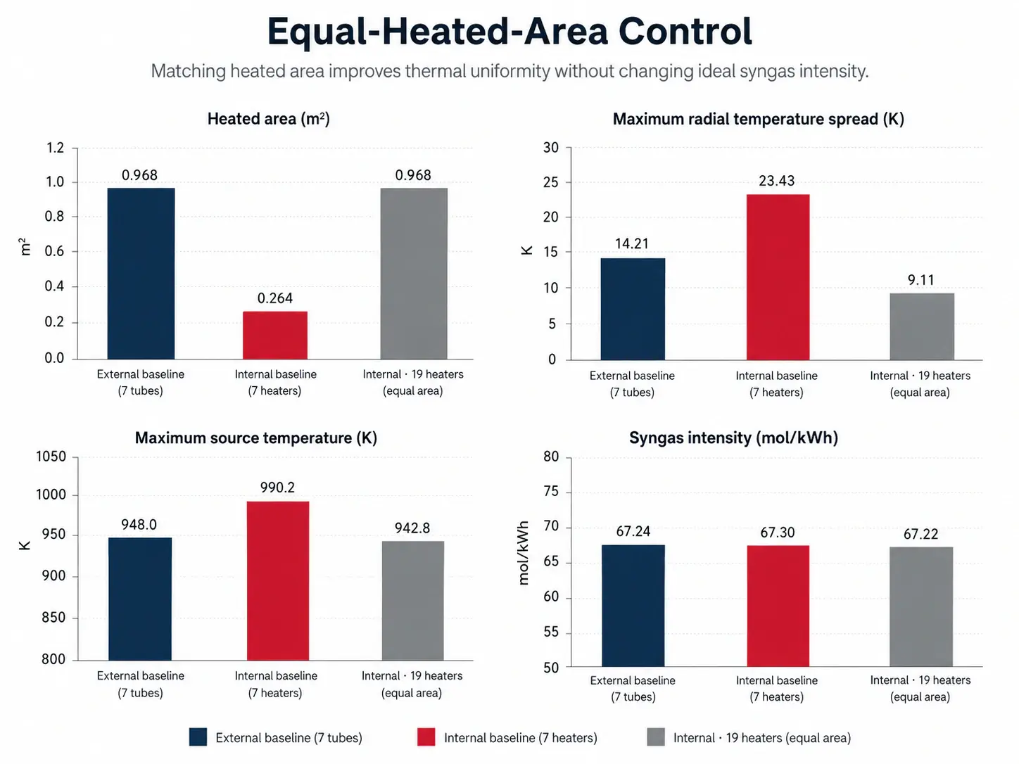
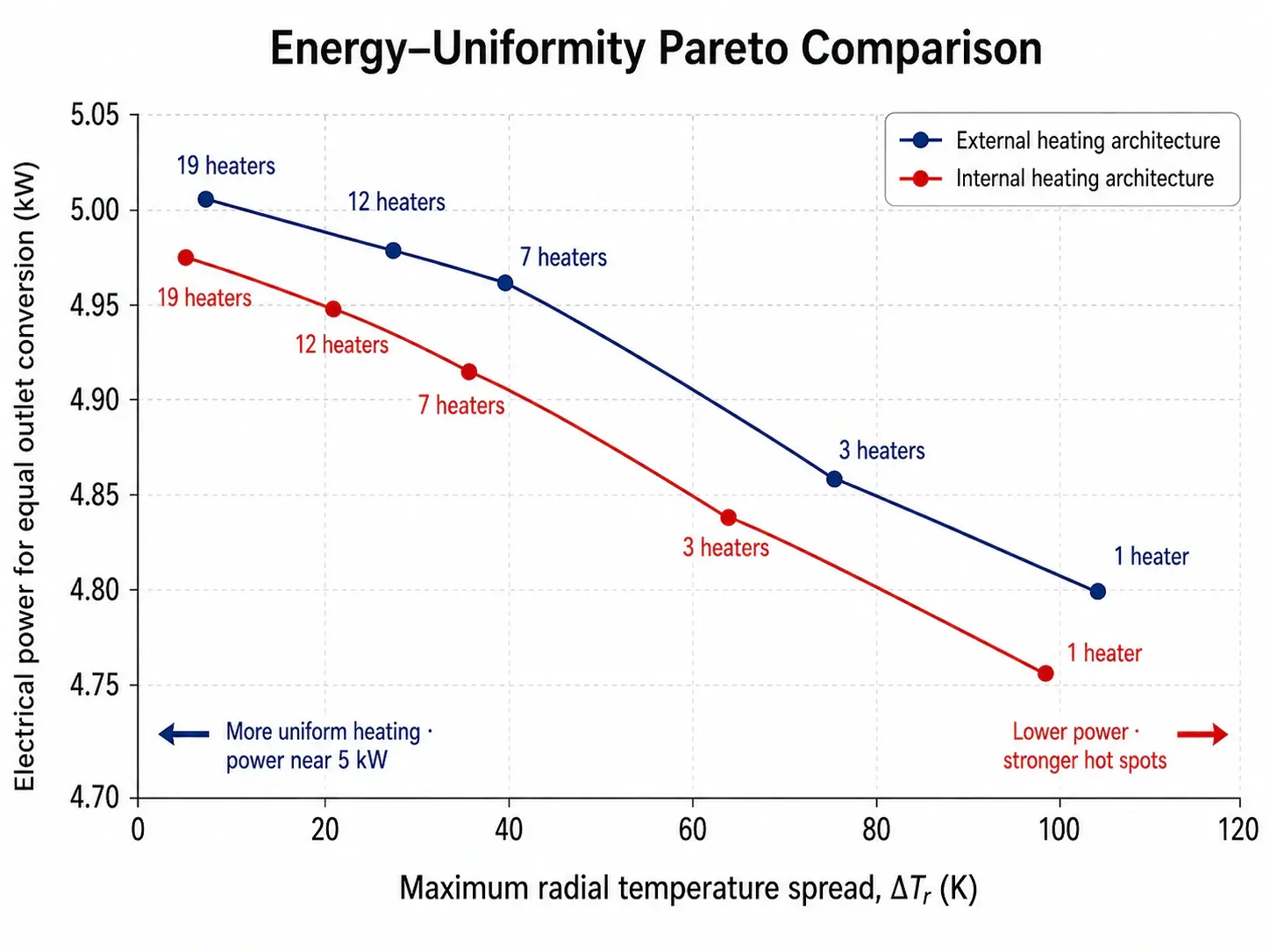
The equal-area and source-count studies make the trade-off much clearer. With 19 internal heaters sized to match the external heated area, the average heat flux returns to 5.17 kW/m², the predicted radial spread falls to 9.11 K, and the source temperature falls to about 942.8 K, while ideal syngas intensity remains essentially unchanged at 67.22 mol/kWh. Distributed area therefore buys temperature uniformity and source-temperature headroom rather than a meaningful ideal-energy gain at this operating point. At the other extreme, a single internal heater reaches the target conversion at only 4.775 kW, but this apparent energy advantage comes with a 103.1 K predicted radial spread and a source temperature of 1345 K. Increasing source count sacrifices very little electrical power while rapidly improving the thermal field. The external architecture follows the same general Pareto behavior, although the penalty associated with concentrated internal heating is more severe. Throughput introduces another constraint. Reducing wet GHSV to 1500 h⁻¹ raises methane conversion to about 54.3% in both reactors, while increasing GHSV eventually makes hydraulics dominant; at 10,000 h⁻¹ the predicted pressure drop approaches 370 kPa from a 500 kPa inlet, making that operating point infeasible for the present bed. The broader bounded uncertainty study varies effective radial conductivity, effectiveness, porosity, pellet diameter, contact conductance, GHSV, and internal heater diameter. The resulting syngas-performance bands overlap, so the model does not support a guaranteed intrinsic advantage for either architecture. The result is better represented as an energy–uniformity–temperature Pareto field than as a single optimum.
Environmental Heat Loss and Reactor Packaging
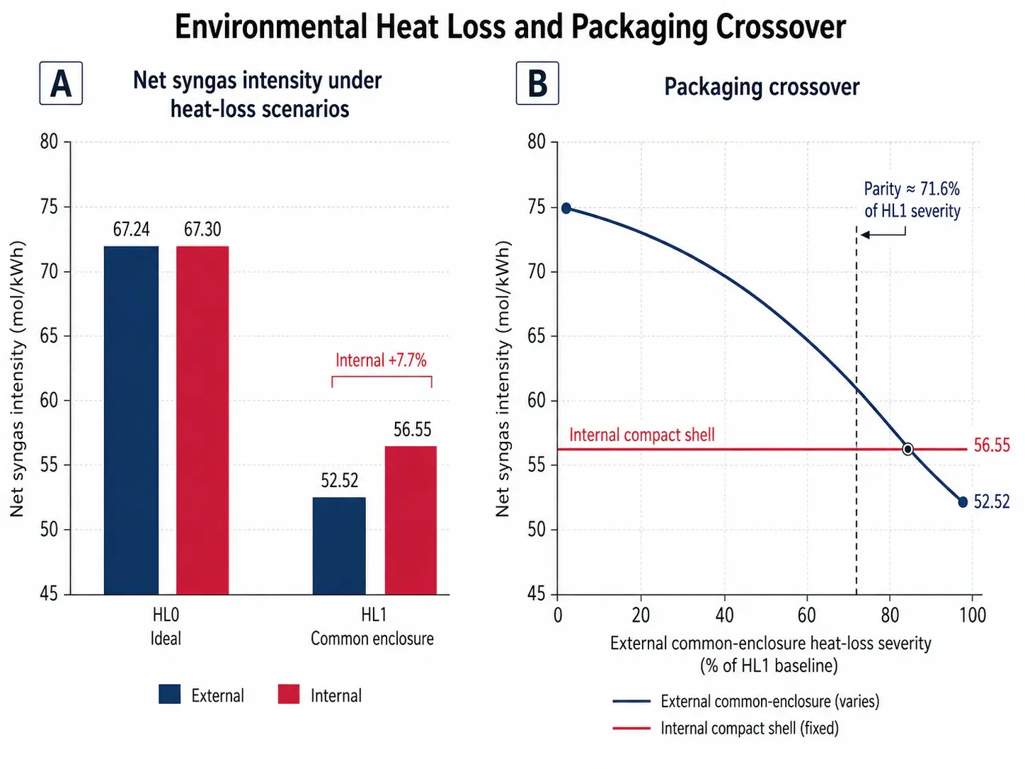
The ranking changes again once environmental heat loss is introduced, but this result is strongly tied to the packaging assumptions. HL0 removes environmental heat loss entirely. HL1, the primary engineering case, places the external tube bundle inside one 100 mm-diameter insulated enclosure and compares it with the compact insulated internal shell. HL2 treats each external tube as individually insulated and is retained as a less favorable external packaging case. Both nonideal cases use 20 mm insulation with thermal conductivity of 0.10 W/m/K, external convection of 10 W/m²/K, emissivity of 0.8, and linearized radiation at a 350 K outer-surface reference. The environmental-loss term is referenced to the outer insulation area, with UA/L multiplying the difference between local reactor gas temperature and ambient in the axial balance; radiation is incorporated into the external film coefficient after linearization. End losses, electrical leads, supports, and penetrations are excluded. Under HL1, the external package loses 1.558 kW and produces 52.52 mol syngas/kWh, while the internal package loses 1.135 kW and produces 56.55 mol/kWh, an advantage of about 7.7%. That should not be interpreted as an intrinsic efficiency advantage of internal heating. It is a result of the selected environmental envelope. When the heat-loss severity of the external common enclosure is reduced to approximately 71.6% of the baseline HL1 value, the two architectures return to parity. The accepted calculations close carbon, hydrogen, and oxygen balances near machine precision; principal-case normalized energy residuals remain below 7 × 10⁻⁸; thermodynamic-cycle identities close at floating-point precision; and independent equilibrium calculations were retained as chemistry checks. Even with those checks, this remains a comparative reduced-order study rather than a validated hardware design. External heating remains attractive when one well-designed common enclosure can limit loss and mechanical simplicity, accessibility, electrical isolation, and replaceability matters. Distributed internal heating becomes more attractive when compact packaging, shorter thermal distance, and source-temperature control carry more weight. The next meaningful step is experimental: measure axial and radial gas and solid temperatures, effective conductivity, contact resistance, environmental heat loss, composition, pressure drop, and entrance-region behavior in a reacting electrically heated packed bed. Only then should absolute conversion, temperature limits, catalyst life, or hardware performance be treated as design guarantees.
Conclusion
The study does not identify a universal winner between external and internal electrical heating, and that is probably the more useful result. At the ideal 5 kW baseline, both reactors give essentially the same methane conversion and syngas intensity, but they arrive there with different thermal fields. The seven external tubes are more uniform because they provide much more heated surface and operate at lower heat flux. When internal heating is distributed over enough area, that disadvantage can be removed and the internal configuration can become thermally better without materially changing ideal syngas production. Once environmental heat loss is included, the smaller internal package gains an advantage under the selected HL1 assumptions, but a better external enclosure can remove that advantage again. The architecture decision is therefore not simply about putting heaters inside or outside the catalyst. It is a coupled balance of heated area, thermal distance, local heat flux, source temperature, catalyst transport, pressure drop, packaging loss, maintainability, and the level of uncertainty that can be accepted before experimental data are available.
About M² Engineering
At M² Engineering, we use physics-based modeling to answer engineering questions before design decisions become expensive. Our work combines CFD, coupled-physics simulation, thermal engineering, process engineering, optimization, and neural operators to understand not only whether a concept works but why it works, where the important limits are, and which assumptions are actually controlling the result. For reactor and thermal-process development, that means looking beyond a single conversion or efficiency number and considering reaction, heat transfer, pressure drop, geometry, uncertainty, and operating constraints together. The objective is not to force a preferred design from a simulation, but to reduce the design space, identify where measurements are still needed, and make the next engineering decision on a stronger physical basis.